

Table of Contents
- Before Testing, Confirm That You Have a Low-Voltage System
- 1. Let the Failure Pattern Determine Where You Start
- 2. Find the Last Verified Good Point on the Correct Branch
- 3. Measure Voltage With the Lights Connected
- 4. Confirm the Suspect Section Before Following a Locator Signal
- 5. Trace the Isolated Cable From Both Ends
- 6. Dig Where the Evidence Agrees
- Test the Repair Before Backfilling
- FAQs
You replaced the bulb, tightened the connector, and reset the transformer. The same section of your yard is still dark. Perhaps you even tried a wire locator, followed its signal across the lawn, and dug where the sound faded—only to find an undamaged cable.
The difficulty is that several different faults can look like a broken underground wire. A corroded splice, a partially damaged conductor, and a loose branch connection can all leave lights dark while producing confusing test results.
To find a broken landscape lighting wire underground, first identify the affected branch, compare voltage at accessible points under normal load, and isolate the suspect cable section. Then use an appropriate underground wire locator from both ends to narrow the search area before digging.
Each test should reduce the amount of cable you still need to investigate.
Before Testing, Confirm That You Have a Low-Voltage System
This guide covers the accessible low-voltage side of landscape lighting systems, commonly operating at 12V or 24V. Check the equipment labels to establish the voltage and whether the output is AC or DC.
Keep household-voltage compartments closed. If the buried circuit supplies 120V or 230V fixtures, or you cannot identify the wiring confidently, have a qualified electrician investigate.
Disconnect power before opening connections, moving conductors, or attaching tracing equipment. Continuity and resistance tests require an isolated, de-energized circuit.
Before digging or inserting a locator’s ground stake, arrange the required utility locating service. In the United States, contact 811 and follow local procedures. Privately installed landscape lighting and irrigation lines may require a separate locate.
For basic diagnosis, gather a suitable multimeter, a compatible working lamp or fixture, wire labels, and a sketch of the layout. An underground wire locator becomes useful after you have narrowed the electrical problem to a particular section.
1. Let the Failure Pattern Determine Where You Start
Before uncovering cable, establish exactly which lights have failed.
| What you observe | What to investigate first |
|---|---|
| Every light is off | Supply power, controls, transformer output, and main connections |
| One fixture is off while others on its branch work | Its lamp, socket, lead, and local connector |
| A group of fixtures has failed together | Their shared branch connection and supply cable |
| Lights become progressively dimmer along a run | Voltage drop, loading, cable sizing, and connection resistance |
| Lights fail intermittently after rain or irrigation | Moisture-sensitive connections or damaged insulation |
These patterns guide the investigation; they do not establish a diagnosis.
Confirm that the low-voltage landscape lighting transformer is supplying the affected output. Use its normal test or manual-on function according to the instructions, so a timer or daylight sensor does not interrupt your measurements.
If only one fixture has failed, test a compatible working lamp where the design permits. If the replacement also stays dark, investigate its connection and supply before replacing more components.
Stop testing and disconnect power if wiring becomes hot, insulation appears damaged, or protection repeatedly trips.
2. Find the Last Verified Good Point on the Correct Branch
A common mistake is assuming that the nearest working light feeds the nearest failed light.
Underground wiring may cross a bed, return toward the transformer, or split at a hidden junction. Fixtures standing next to each other can belong to different branches.
Sketch what you can establish:
- Which cable leaves each transformer output.
- Where accessible splices or hubs are located.
- Which fixtures share a confirmed cable route.
- Where recent edging, planting, staking, or construction occurred.
Your goal is to identify two electrically connected test points with different results: an upstream point that supplies the load correctly and a downstream point that does not.
That interval becomes the suspect section.
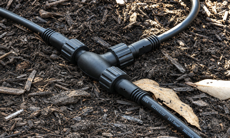
A T-shaped low-voltage landscape lighting connector splits power between multiple cable branches, making it an important connection point to inspect when several lights fail simultaneously.
For example, if three lights share a branch and all three failed immediately after a new shrub was planted, check the branch’s supply connection first. If that connection is sound, the newly disturbed route deserves attention.
The timing of the failure helps prioritize locations, but measurements should decide which section remains suspect.
If an accessible junction lies between your two test points, test there next. This can shorten the search substantially. Avoid cutting healthy cable merely to create another test point.
3. Measure Voltage With the Lights Connected
“I measured voltage, so the wire must be fine” is one of the most misleading conclusions in landscape lighting troubleshooting.
A multimeter draws very little current. A deteriorated connection may show an apparently reasonable voltage with the fixture disconnected, then lose substantial voltage when the lights attempt to operate.
Where the equipment allows safe access, measure with the normal lighting load connected. Testing a lamp circuit without its lamp can produce a misleading result.
Set the meter to the appropriate AC or DC voltage range. Use the COM and voltage terminals, and measure across the two supply conductors at the test point. Soil and nearby metalwork are not suitable reference points for this comparison.
Take readings at:
- The transformer’s accessible low-voltage output.
- The upstream end of the suspect section.
- The downstream end of that section.
Compare the results with the fixture’s specified input range.
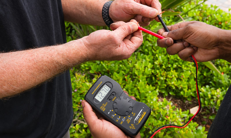
As an illustrative example, suppose the transformer maintains 12.6V, an upstream junction measures 12.3V, and the next junction falls to 5.2V while the affected lights are connected. That directs attention to the cable and connections between those junctions. It does not reveal the exact underground location.
Keep the load configuration consistent between readings. Disconnecting several fixtures halfway through testing can make a resistive fault appear to improve.
Distinguish a Local Fault From General Voltage Drop
A substantial change across one short interval calls for inspection of that interval and its connections. A gradual reduction along a long, heavily loaded run also requires a review of cable sizing and layout.
Run length, connected load, and conductor size all affect delivered voltage. Check landscape lighting wire size before treating every dim fixture as evidence of a severed cable. Fixture voltage must remain within the equipment’s specified operating range.
Raising the transformer tap before resolving a deteriorated connection can hide the symptom and leave the underlying fault in place.
4. Confirm the Suspect Section Before Following a Locator Signal
Two tests can help establish whether your investigation has reached the right section.
Use Continuity to Check for an Open Circuit
Continuity testing is useful only when you know what you have isolated. Connected fixtures, transformer windings, and alternative paths can interfere with interpretation.
For an isolated two-conductor cable section with accessible ends:
- Disconnect power and verify that voltage is absent.
- Disconnect the section from the transformer, fixtures, and other branches.
- Check the meter by touching its probes together.
- Temporarily join the two conductors at the far end.
- Measure resistance across the two conductors at the near end.
- Remove the temporary join before restoring any connections or power.
An open reading indicates that the test loop is incomplete. Check probe contact and the temporary join before concluding that a conductor is broken.
A continuity beep establishes that a path exists. It does not establish that the path has sufficiently low resistance to operate the lights properly. Beeper thresholds vary between meters, and the test uses only a small current.
If you cannot account for intermediate taps or parallel connections, the result may remain inconclusive.
Use a Temporary Bypass to Test the Diagnosis
A temporary replacement cable can help confirm a suspect interval before you excavate it.
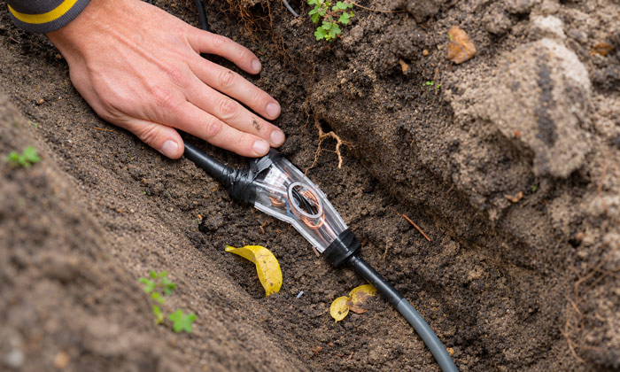
An underground landscape lighting junction box connects cable sections and provides an accessible point for isolating and testing a suspect circuit.
With power disconnected, isolate both conductors of the suspect section at both ends. Connect a suitable temporary cable between the same upstream and downstream points, accounting for any intermediate branches.
Restore power briefly and test the normal downstream load. Protect the temporary cable and connections from damage and foot traffic throughout the test.
If normal operation returns, you have evidence against the original section or its endpoint connections.
That result identifies an interval, not necessarily a break in the buried cable. A failed connector at either end can produce the same improvement.
Remove the temporary arrangement after testing. A loose cable across the lawn should not become a permanent repair.
5. Trace the Isolated Cable From Both Ends
Once you have confirmed the suspect section, use a locator intended for buried cable and suitable for the fault you are investigating.
Check its operating instructions carefully. A tool that traces an intact cable route may have limited ability to identify an open conductor. Detection also depends on burial conditions, depth, and the cable’s surroundings.
Federal Highway Administration. (n.d.). Underground utilities—Cable and pipe locators. U.S. Department of Transportation.
Connect the Transmitter for the Correct Application
Keep the circuit de-energized and isolate the target cable as required by the locator’s instructions.
Use the specified connection arrangement for open-wire tracing. Some instruments require a separate ground return or particular treatment of unused conductors. Connecting the clips arbitrarily across a cable pair can produce an unhelpful signal.
Begin near a known part of the route, then trace slowly while keeping receiver orientation and height consistent.
Mark the route and any repeatable change in signal.
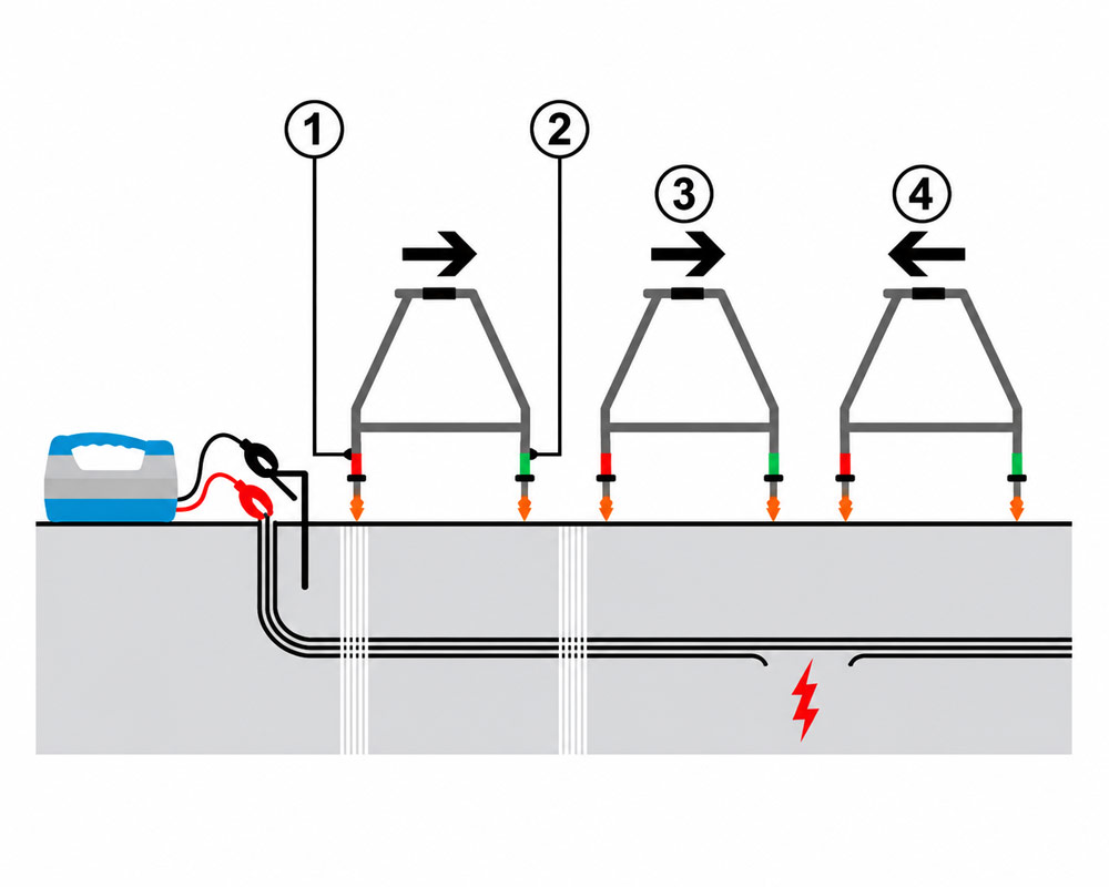
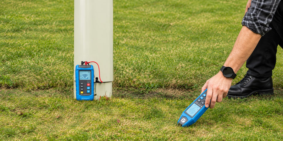
An underground cable locator traces a buried cable from opposite ends to help identify and confirm the suspected fault section.
Repeat the Trace From the Opposite End
Where both ends are accessible and the equipment supports the procedure, move the transmitter to the other end and trace back.
Compare the two results. A repeatable boundary approached from opposite directions provides more useful evidence than a single weak reading.
However, a partially open, high-resistance fault may still transmit a tracing signal even when it cannot carry the lighting load. Some tracer instructions explicitly identify this limitation. Underground materials can also make tracing difficult.
Understand Why a Signal Can Mislead You
A fading signal may reflect a bend, changing depth, an unsuitable setup, or interference.
Signals can also couple onto nearby conductors, leading you away from the intended cable. Where the equipment permits, an appropriate connection method and lower tracing frequency can help reduce unwanted coupling.
If the receiver gives a broad response everywhere, check sensitivity before marking a digging location. Increasing sensitivity repeatedly can make a vague result harder to interpret.
When tracing and electrical tests disagree, revisit the setup and branch identification before opening another hole.
6. Dig Where the Evidence Agrees
Choose your first inspection area by combining the evidence you have collected:
- The electrically confirmed suspect interval.
- A repeatable tracing change.
- An accessible splice or branch junction.
- A location disturbed shortly before the failure.
This approach gives each inspection opening a clear purpose.
After completing the required locating procedures, expose the area carefully using methods appropriate to local utility clearances. Avoid blindly driving a probe or shovel along the suspected route.
Inspect connectors as closely as the cable itself. Look for loose conductors, broken strands, corrosion, damaged insulation, and signs of moisture entry.
If you uncover an undamaged cable, use the opening to verify the route and reassess the evidence. Expanding the hole without a new reason rarely improves the diagnosis.
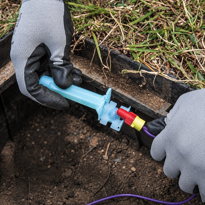
A technician installs a waterproof direct-burial connector to create a secure, moisture-resistant splice in an underground landscape lighting cable.
Repair Sound Cable With Suitable Connections
Disconnect power before making the repair.
Remove damaged material until the remaining conductor and insulation are sound. If reaching sound cable leaves insufficient length, install an appropriate replacement section rather than stretching the existing ends together.
Use connectors specifically approved for the cable type, conductor combination, and below-grade conditions. Direct-burial connectors are designed for exposure that ordinary indoor connectors are not intended to withstand. Follow their preparation and installation instructions, including any single-use restriction.
Electrical tape alone should not serve as the underground splice system.
Restore protected cable routing, leave suitable service slack, and avoid pulling the repaired joint tight.
Know When Replacing the Section Makes More Sense
A localized cut in otherwise sound cable may be a reasonable repair.
Replacement deserves stronger consideration when you find several deteriorated joints, extensive insulation damage, or corrosion continuing beyond the exposed area. Compare the work needed to replace the confirmed interval with the additional locating and restoration required to keep searching.
Finding the smallest possible defect is useful only if the resulting repair will be dependable.
Test the Repair Before Backfilling
Reconnect the normal load and repeat the measurements that originally identified the fault.
Confirm that:
- The affected fixtures operate together.
- Their input voltage stays within the specified range.
- Other branches still work correctly.
- The repaired connections remain mechanically secure.
- Normal controls operate through their intended cycle.
If the original failure occurred intermittently, one successful switch-on provides limited reassurance. Observe the system again under the conditions associated with the failure, without deliberately exposing electrical equipment to water.
Before covering the repair, photograph the route and record the splice location against a fixed reference, such as a path corner or wall.
Your next troubleshooting session should begin with a known layout and previous readings.
FAQs
1. How Deep Should Landscape Lighting Wire Be Buried?
Follow the applicable local requirements and the installation instructions for the actual cable and lighting system. There is no single burial depth that applies to every landscape lighting installation.
Check instructions for the main supply cable and individual fixture leads separately. A depth restriction for a short fixture lead should not automatically be applied to the entire underground run. Also consider exposure to edging, aeration, and future planting.
2. Can a Metal Detector Find a Broken Landscape Lighting Wire?
A metal detector may help indicate buried metal, but it cannot establish whether a conductor is electrically intact.
A clean break can leave almost all the metal in its original position, so a detector response may continue across the damaged location. It also cannot reliably distinguish your lighting cable from unrelated buried metal.
3. Can I Replace Landscape Lighting Wire Under a Driveway Without Removing the Concrete?
Possibly, if the cable runs through a continuous, serviceable conduit with accessible ends. Confirm the conduit’s condition, available space, and pulling requirements before attempting replacement.
Use cable suitable for the underground environment. Do not assume the damaged wire will survive being used as a pulling line. If there is no usable conduit, a qualified contractor may need to assess a new route or a boring method.
4. Can I Connect Different Wire Gauges in a Landscape Lighting Circuit?
Different gauges may be connected when the equipment and connector instructions permit the exact conductor sizes, types, and quantities involved.
The smaller conductor still needs to be suitable for the current it carries, and its length contributes to voltage drop. Adding a thicker section elsewhere does not eliminate those constraints. Evaluate each section’s load and resistance before choosing a repair cable.
5. Does an IP65-Rated Fixture Make Its Underground Connections Waterproof?
No. A fixture’s IP65 rating describes protection provided by its enclosure. It does not extend automatically to separate cable joints.
Select underground connectors independently for their installation environment. A suitably rated fixture can still stop working because its external connection was assembled with components unsuitable for burial.
