
Table of Contents
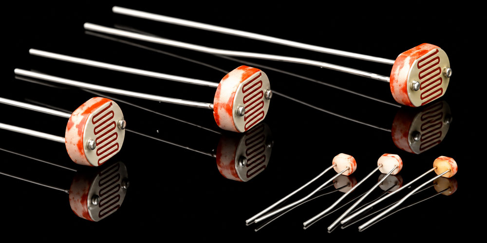
A light-dependent resistor (LDR), also called a photoresistor, is a passive electronic component whose resistance falls as more light reaches its sensing surface and rises as that surface gets darker. Connected in a voltage divider, it produces a voltage that a controller can use to detect a change in light level. In an outdoor fixture, that signal can tell the controller when to switch the lamp on at dusk and off at dawn.
Two fixtures on the same property can switch on at different times. A sensor under a deep eave may already be in shadow while a sensor facing open sky still receives daylight. Both can be working correctly. Each is responding to the light at its own sensing window, which makes sensor placement part of the lighting design.
How Does a Light-Dependent Resistor Work?
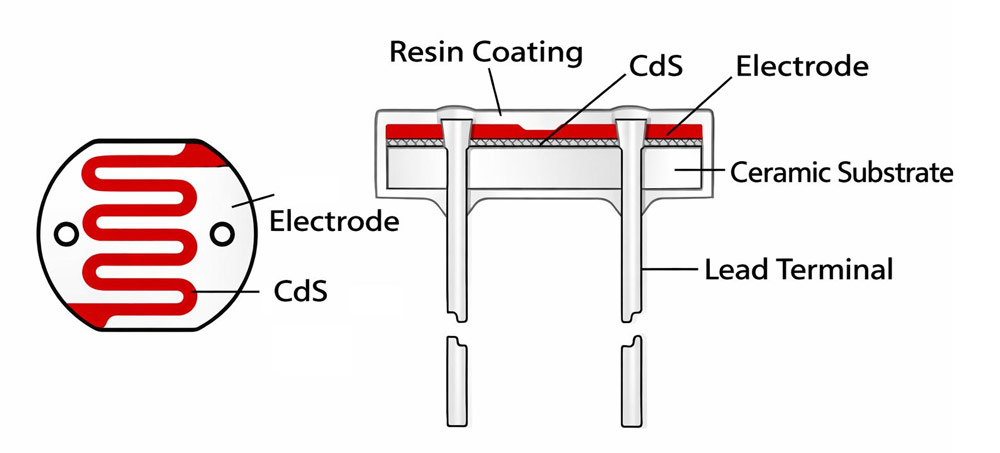
The internal structure of a light-dependent resistor (LDR) typically consists of a transparent protective coating, a cadmium sulfide (CdS) photosensitive layer, interdigitated metal electrodes, and a ceramic substrate. When light strikes the photosensitive material, its conductivity increases, causing the resistance to decrease as light intensity rises.
An LDR contains a light-sensitive semiconductor between two electrodes. When the material absorbs photons with sufficient energy, they create mobile charge carriers. More carriers allow more current to flow at the same applied voltage, so the resistance falls. This effect is called photoconductivity. As the light fades, the carrier population falls and the resistance rises again.
The change is continuous. During twilight, the resistance moves through a range of values before the lighting controller decides to switch. The relationship is also nonlinear. Two equal increases in illuminance at different points on the response curve can produce different changes in resistance.
That behavior suits applications such as daylight switches, simple brightness controls and slow beam-interruption detection. In each case, the circuit needs a reliable change in signal over a particular operating range. For a dusk switch, the most important part of the response curve is the narrow range around the light level at which the fixture should come on.
How a Voltage Divider Reads an LDR
A simple sensing circuit connects a fixed resistor from the supply to a sensing node and the LDR from that node to ground. A comparator or microcontroller reads the voltage at the junction. If the input draws negligible current, the voltage is:
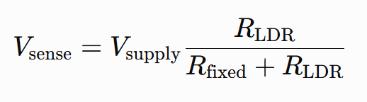
In this configuration, the sensing voltage rises as it gets darker. The following example uses a 3.3 V supply and a 22 kΩ fixed resistor. The LDR resistance values are illustrative.
| Light condition | LDR resistance | Sensing voltage |
|---|---|---|
| Bright | 4.7 kΩ | 0.58 V |
| Intermediate | 22 kΩ | 1.65 V |
| Dark | 220 kΩ | 3.00 V |
To choose the fixed resistor, start with the LDR resistance near the intended switching light level. A fixed resistor close to that value puts the sensing voltage near half the supply. Around that point, the divider gives its largest voltage change for a small percentage change in LDR resistance. This makes the circuit more responsive to changes in the range where a switching decision matters.
The controller then compares the sensed voltage with a threshold. In the example above, a turn-on threshold of 1.80 V corresponds to an LDR resistance of 26.4 kΩ. The illuminance that produces that resistance depends on the specific sensor, the light source and the installed sensing window.
What to Check in an LDR Datasheet
A catalog resistance value describes the sensor under specified test conditions. When selecting an LDR for a lighting control, pay attention to the conditions attached to each number.
| Datasheet parameter | What it tells you |
|---|---|
| Light resistance | The resistance or resistance range at a specified illuminance. The range helps you estimate how far the switching point could vary from one unit to another. |
| Dark resistance | The resistance after a specified period in darkness. The elapsed time matters because resistance can continue rising after the light is removed. |
| Spectral response | The wavelengths to which the sensor is most sensitive. A tinted cover or a different light source can change the reading at the same illuminance. |
| Rise and decay times | How quickly the sensor responds to changes in illumination. Check the stated test conditions for both directions. |
| Operating temperature and electrical ratings | The conditions within which the device can operate, including allowable voltage and power dissipation. |
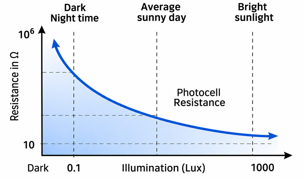
LDR resistance falls as light levels rise, so compare datasheet resistance values at the same illuminance in lux.
The same lux reading can give two different LDR readings. Illuminance in lux weights wavelengths according to the standard sensitivity of human daytime vision. An LDR has its own spectral response. Twilight and a warm-white lamp can produce the same illuminance at the sensing window while driving the photoresistor to different resistance values.
Recent exposure also matters. A photoresistor brought out of darkness can take time to settle, and its response can vary with temperature. To set or compare switching thresholds, use the finished sensing window and let the readings stabilize under consistent conditions. A bench lamp is useful for checking that the circuit responds. Outdoor twilight is the better condition for confirming when an installed dusk switch actually operates.
How Outdoor Lights Use an LDR Signal
In an outdoor fixture, the sensor provides the input and the controller makes the switching decision. The controller reads the sensor and commands the LED driver or a separate switching stage. In lighting specifications, photocell can refer to the sensing element or to a complete light-operated control.
Some controls combine a light threshold with a schedule. A photocell landscape lighting timer can start the lights when the garden gets dark and switch them off at a programmed hour. The start time can move with the seasons while the shutoff time stays fixed.
In battery-powered solar lights, the photovoltaic panel charges the battery during the day. Some designs also monitor the panel voltage to infer when darkness has arrived. Others use a dedicated ambient-light sensor. When the panel supplies the daylight signal, its orientation affects both charging and switching. With a separate sensor, designers can give the charging panel and sensing window different views of the surroundings.
Why a Dusk-to-Dawn Light Can Keep Turning On and Off
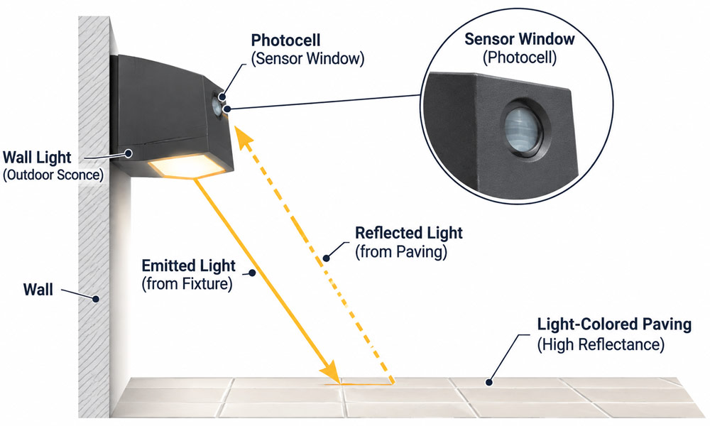
Consider a wall light mounted above pale paving. At dusk, the sensor calls for the lamp to turn on. The paving then reflects some of the lamp’s output back into the sensing window. If enough reflected light reaches the LDR, the controller can switch the lamp off. The reflection disappears, the reading returns to its darker value, and the cycle starts again.
A controller can use two thresholds, a technique called hysteresis. With the divider from the earlier example, suppose the controller turns the lamp on at 1.80 V as it gets darker and off at 1.50 V as it gets brighter. Between those thresholds, it keeps the current lamp state.
Now consider three illustrative readings near dusk:
| Condition | Sensing voltage | Effect on the controller |
|---|---|---|
| Lamp off, with twilight reaching the sensor | 1.82 V | The reading crosses the turn-on threshold. |
| Lamp on, with reflected light reaching the sensor | 1.43 V | The reading crosses the turn-off threshold. |
| Lamp on, after aiming the sensor away from the reflection | 1.67 V | The reading stays 0.17 V above the turn-off threshold. |
In the third case, the sensor still sees a change when the lamp comes on, but that change stays within the switching band. The lamp can remain on. The 0.17 V margin describes the illustrated installation under those conditions. A different fixture angle, brighter output or a reflection from wet paving can change it.
A switching delay addresses brief changes. For example, a controller can require the signal to stay beyond a threshold for a set time before responding to a passing headlight. A reflection that continues for as long as the lamp is on can outlast that delay. In that case, changing where the sensor looks or adjusting the switching band addresses the cause of the cycling.
How to Check the Sensor at the Installation Site
Check the fixture close to the intended dusk switching point. A test after full darkness can miss a feedback problem because the sensor is already well past its turn-on threshold. On a low-voltage prototype with access to the sensing signal, compare readings with the lamp off and on while the ambient light is approximately steady. On a finished fixture, observe the transition with the lamp at normal output and nearby lights in their usual nighttime state.
If re-aiming or shielding the sensor improves the dusk transition, check the dawn transition as well. The same adjustment can reduce the daylight reaching the sensing window. Recording both switch times and the final sensor position gives you a baseline if a fixture, window cover or nearby surface changes later.
FAQs
1. Does a light-dependent resistor have polarity?
A bare two-lead LDR is nonpolarized, so either lead can go on either side of the connection. A sensor module containing an LDR and additional electronics can have designated supply, ground and output pins. Follow the markings on the module.
2. How do you test an LDR with a multimeter?
Set the meter to resistance and measure across the unpowered LDR. If it is mounted on a circuit board, isolate one lead so other components cannot affect the reading. Measure it under steady light, then cover the sensing surface with an opaque object and let the reading settle. A working LDR should show a clear increase in resistance when covered. Use a higher resistance range if the dark reading exceeds the meter’s selected range.
3. What is the difference between an LDR and a photodiode?
An LDR changes resistance in response to light. A photodiode is a semiconductor junction that generates a photocurrent when illuminated. A suitable readout circuit converts that current into a usable signal. Photodiodes generally respond faster, making them suitable for optical pulses, rapidly changing light and brief beam interruptions.
4. Can a photocell and a motion sensor control the same outdoor light?
Yes. A photocell can enable the fixture after dusk, while PIR or radar motion detection determines when the controller raises the output. A fixture with a dim standby mode can maintain a low background light level, brighten when someone passes and return to standby after a preset interval.
5. How can you tell whether a solar light has a sensor problem or a weak battery?
For a solar light that stays off at night, start with a charged fixture in its normal operating mode. Cover the dedicated sensing window or, on a fixture that uses the panel for detection, cover the panel. Allow time for the switching delay. If the lamp turns on and stays lit during the test, check for nighttime light reaching the sensor at its installed location. If it starts and fades quickly after a full charge, check battery capacity and the charging path first.
